To connect different locations with each other the word ‘IPSEC’ comes up very quickly. At the same time, if you mention the word ‘IPSEC’ to a lot if not most IT Pro’s they will cringe. They will think about the numerous times trying to get tunnel up or debugging a stability issue with one of the tunnels.
‘IPSEC’ is not the most user-friendly protocol in the world. It is a standard developed in a large committee to create something that was versatile but it made it also quite complex. This leads to the implementations of the standard to be ever so slightly out of sync with each other. Connection vendor A with vendor B or with open source implementation C can be a daunting task and some say: “it is black magic”.
Recently, I worked on a project to connect 2 firewalls, I know quite well, using IPSEC. In the blue corner the challenger of today Barracuda CloudGen Firewall and in the red corner Fortinet’s FortiGate Next-Gen Firewall.
A year or 2 ago, I already had worked on this and I had a configuration documented but that never got onto the blog.
Using a policy-based setup, the networks on both sides are defined statically in the configuration and during the negotiation of the IPSEC VPN tunnel. If you later want to change it you need to configure both sides again.
In large networks, this is not very flexible. A lot of these larger networks use routing protocols to announce to their neighbors their internal networks. The requirement for this setup was to have a route-based IPSEC VPN.
Network setup
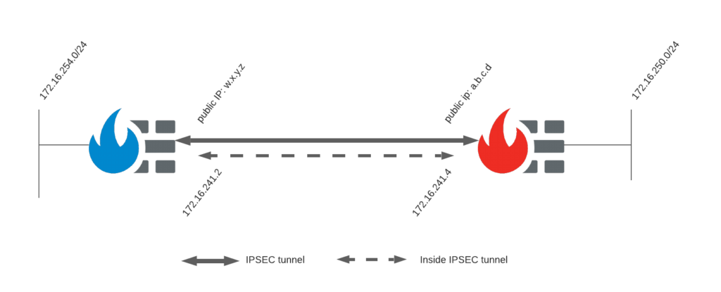
Drawing
To get this going, I built a little demo set up here to test this out. Both units receive a public IP via DHCP from my ISP. Each has a private network attached and on both sides, we have a numbered tunnel interface. This allows us to route traffic destined for the VPN tunnel to this interface. We can even route it not only to the interface but also to the IP inside the tunnel on the other side.
The firmware of both appliances tested in this setup:
- FortiGate version 6.4.2
- Barracuda CloudGen Firewall 8.0.2
ISPEC Tunnel settings
Besides this drawing, we need to agree on certain parameters. These are used to negotiate the successful creation of an IPSEC VPN tunnel. Each IPSEC VPN tunnel has 2 phases that require negotiation. Phase 1 will establish a secure encrypted channel for both sides to negotiate phase 2. Once Phase 1 is completed successfully an IKE Security Association (SA) indicates this agreement. Phase 2 will determine how the traffic will be encrypted and send between both units. An IPSEC Security Association (SA) is created on completion and used to reference this agreement on both sides.
More information is available on mutliple sites on the internet like this one.
- IPSEC IKEv1
- Phase 1:
- Encryption: AES 256
- Authentication: SHA 256
- Diffie-Hellman Group: 2
- Pre-shared key: [keep it safe]
- Mode: main
- Death Peer Detection (DPD) interval: 5s
- Key Lifetime: 28800
- Phase 2:
- Encryption: AES 256
- Authentication: SHA 256
- Diffie-Hellman Group: 2
- Perfect Forward Secrecy (PFS)
- Key Lifetime: 3600
- Phase 1:
In each firewall, 3 sections needs to be adapted: IPSEC VPN, routing, firewall policy.
Configuration
FortiGate Next-Gen Firewall
The FortiGate can be configured via the GUI or CLI. For completeness, you can find the snippets from the configuration file below the screenhots.
IPSEC VPN
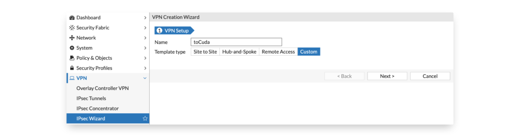
In the FortiGate GUI go to VPN > IPSEC Wizard and create a custom VPN tunnel:
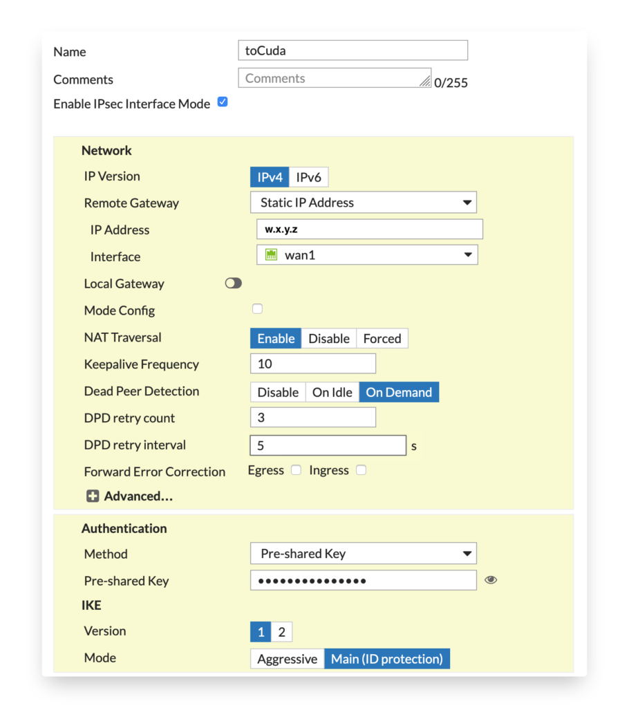
Configure Phase 1 according to the agreed parameters.
Notice that you need to replace the w.x.y.z with the public IP of the Barracuda side. The external interface can be different for your deployment.
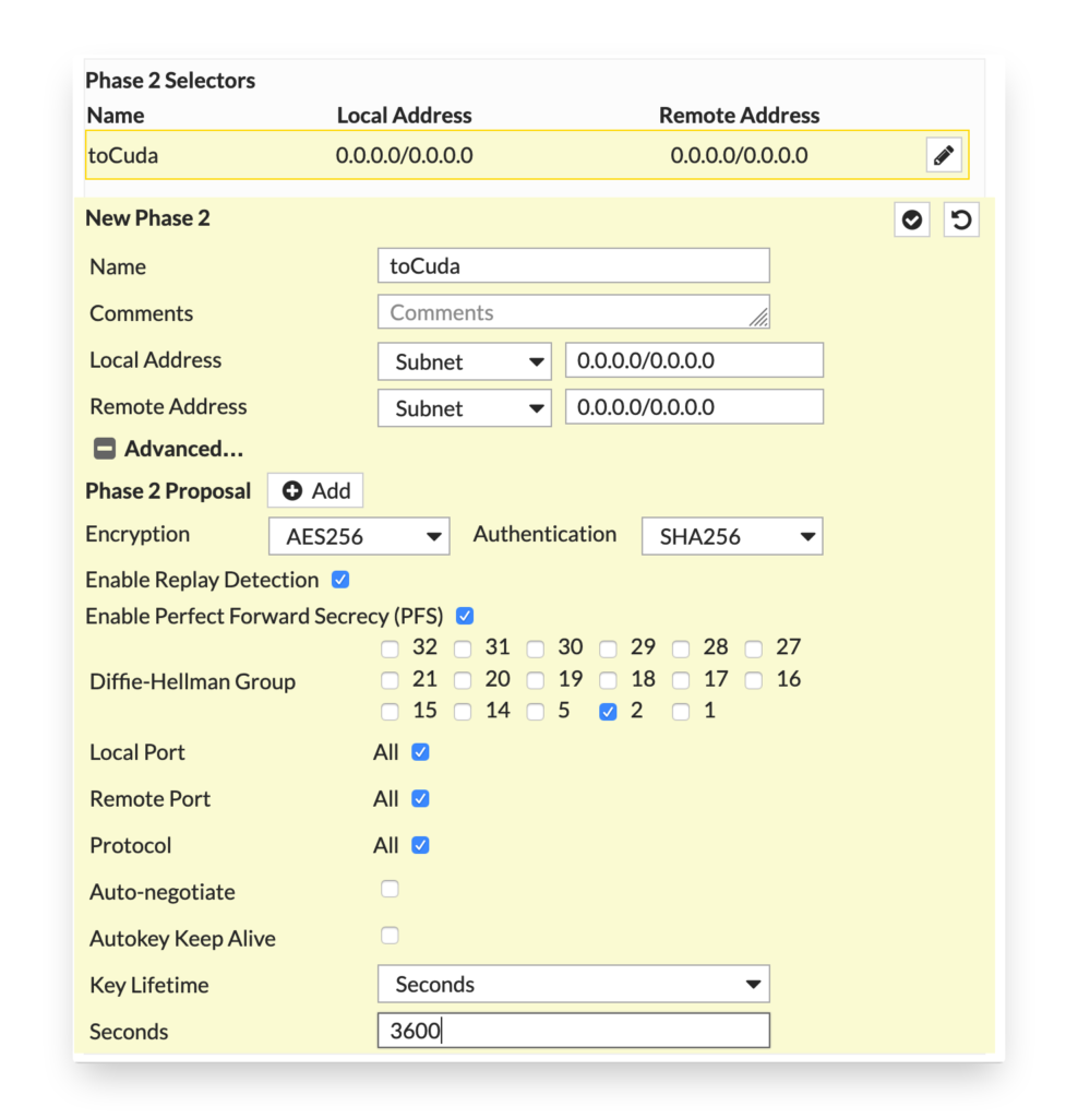
Next up are the Phase 2 parameters. The selectors will be left to ‘0.0.0.0/0.0.0.0’ so that we can use routing to direct traffic to the tunnel.
Via the CLI the configuration would look something like this:
config vpn ipsec phase1-interface
  edit "toCuda"
    set interface "wan1"
    set keylife 28800
    set peertype any
    set net-device disable
    set proposal aes256-sha256
    set dhgrp 2
    set auto-discovery-sender enable
    set auto-discovery-receiver enable
    set remote-gw w.x.y.z
    set tunnel-search nexthop
    set psksecret yourkey
    set dpd-retryinterval 5
  next
end
config vpn ipsec phase2-interface
  edit "toCuda"
    set phase1name "toCuda"
    set proposal aes256-sha256
    set dhgrp 2
    set keylifeseconds 3600
  next
end
Send the pre shared key via a different medium as the rest of your configuration. This will make it harder for a 3rd party to intercept all information to decrypt/intercept traffic.
Network Interface
As we are using routing via an interface we setup an IP range inside the tunnel. Configure the IP on the tunnel interface linked to your external network interface.
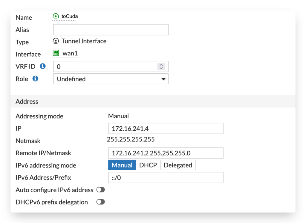
config system interface
    edit "toCuda"
        set vdom "root"
        set ip 172.16.241.4 255.255.255.255
        set allowaccess ping
        set type tunnel
        set remote-ip 172.16.241.2 255.255.255.0
        set interface "wan1"
    next
end
Routing
After the IPSEC tunnel settings have been configured we need to route traffic to the tunnel. It is recommended to configure both the route to the IPSEC tunnel as well as a ‘Blackhole’ destination with a lower priority. In case the tunnel is not up the traffic will be not routed via the default gateway.
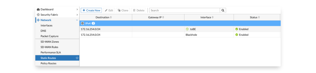
CLI configuration of the static routes:
config router static
  edit 1
    set dst 172.16.254.0 255.255.255.0
    set device "toCuda"
  next
  edit 2
    set dst 172.16.254.0 255.255.255.0
    set distance 20
    set blackhole enable
  next
end
You can also use policy based routing to create forced tunneling. This will force, in the below example, all traffic (0.0.0.0/0) from a specific network W32 to be routed across the VPN. Traffic from other networks is not affected by this route.
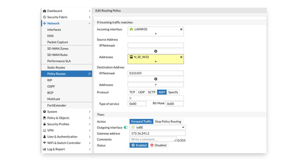
It is nice in the configuration that you can use the source address for the policy based routing using a firewall object. That way you only need configure it once.
config firewall address
  edit "N_SE_W32"
    set subnet 172.16.252.0 255.255.255.0
  next
end
config router policy
  edit 1
    set input-device "LANW32"
    set srcaddr "N_SE_W32"
    set dst "0.0.0.0/0.0.0.0"
    set gateway 172.16.241.2
    set output-device "toBE"
  next
end
Firewall policy
A FortiGate IPSEC tunnel only becomes active when a firewall policy is available. The third steps after the IPSEC tunnel and routing is to configure it. Here we allow traffic fro the local LAN (N_SE_LAN) to a LAN called N_BE_LAN.
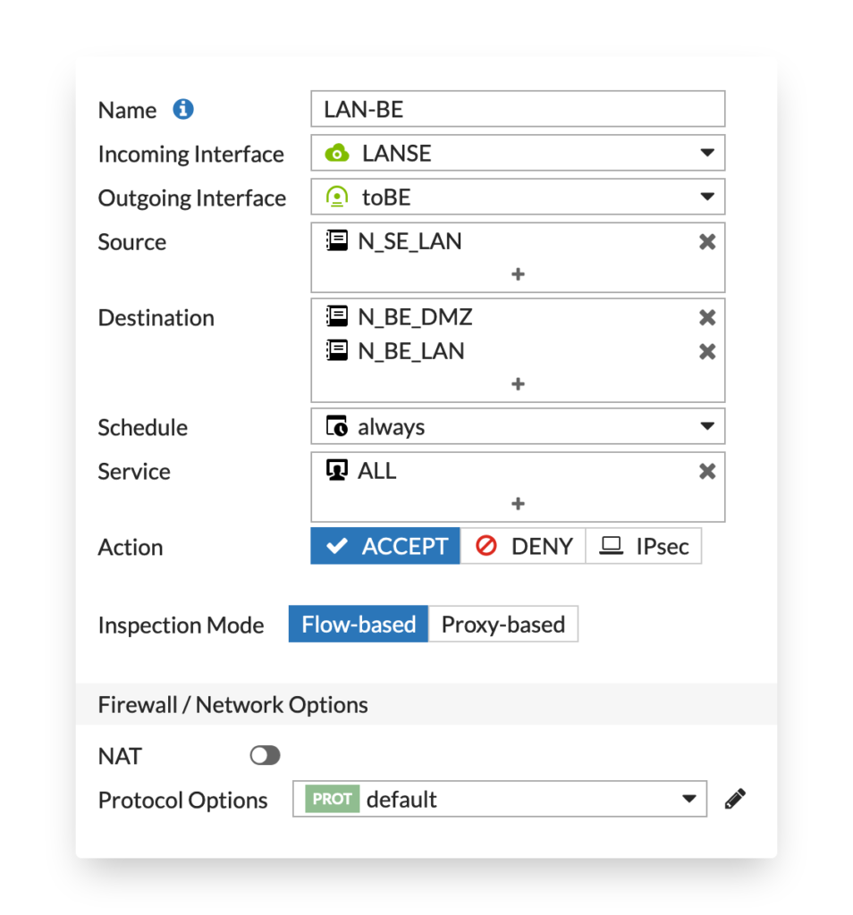
config firewall address
  edit "N_BE_LAN"
    set subnet 172.16.254.0 255.255.255.0
  next
end
config firewall address
  edit "N_BE_DMZ"
    set subnet 172.16.253.0 255.255.255.0
  next
end
config firewall address
  edit "N_SE_LAN"
    set subnet 172.16.250.0 255.255.255.0
  next
end
config firewall policy
  edit 0
    set name "LAN-BE"
    set srcintf "LANSE"
    set dstintf "toBE"
    set srcaddr "N_SE_LAN"
    set dstaddr "N_BE_LAN"
    set action accept
    set schedule "always"
    set service "ALL"
    set logtraffic all
  next
end
If you have forced tunneling configured and want to route all traffic over the IPSEC tunnel you also need a matching firewall policy. In the firewall policy, we allow traffic from N_SE_W32 to all networks (0.0.0.0/0) to go via the IPSEC tunnel.
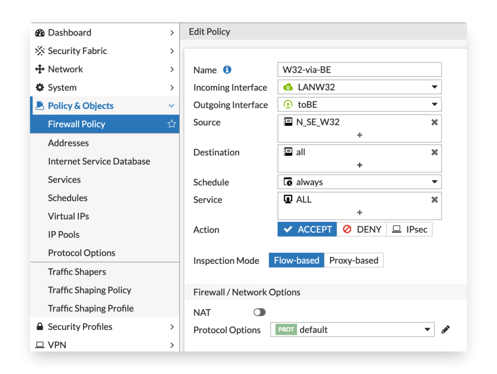
config firewall policy
  edit 0
    set name "W32-via-BE"
    set srcintf "LANW32"
    set dstintf "toBE"
    set srcaddr "N_SE_W32"
    set dstaddr "all"
    set action accept
    set schedule "always"
    set service "ALL"
    set logtraffic all
  next
end
Barracuda CloudGen Firewall
The Barracuda CloudGen Firewall is configured via the windows admin GUI.
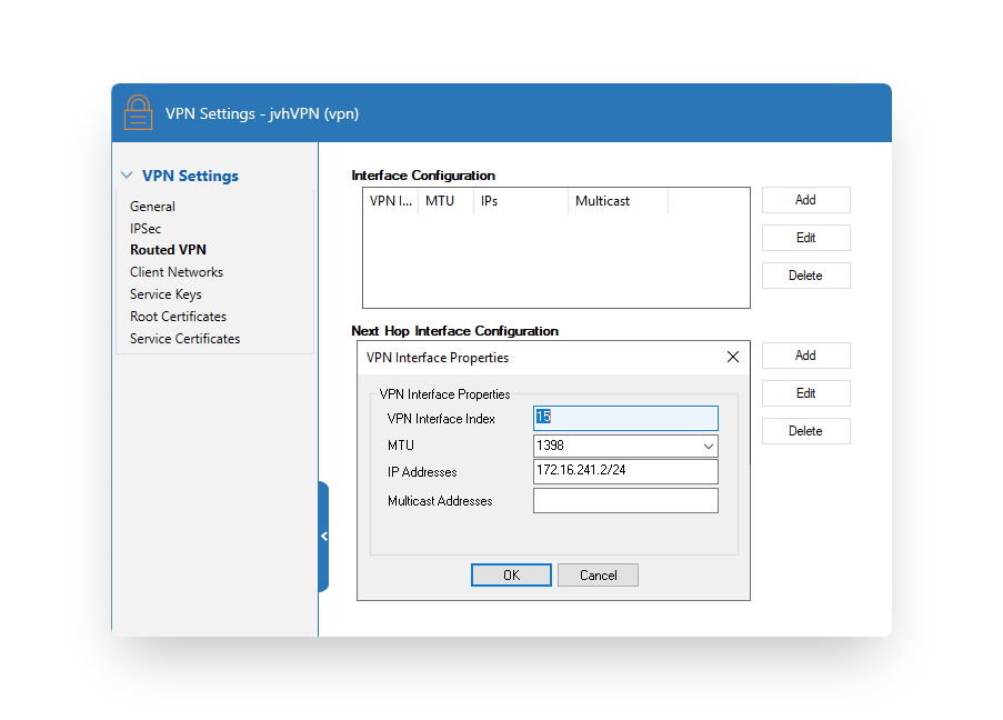
VPN Tunnel Interface
First of all, a numbered VPN tunnel interface needs to be configured in Configuration > VPN Settings > Routed VPN. Once done verify the network activation Control > Box > Network > Activate New Network Configuration.
IPSEC VPN
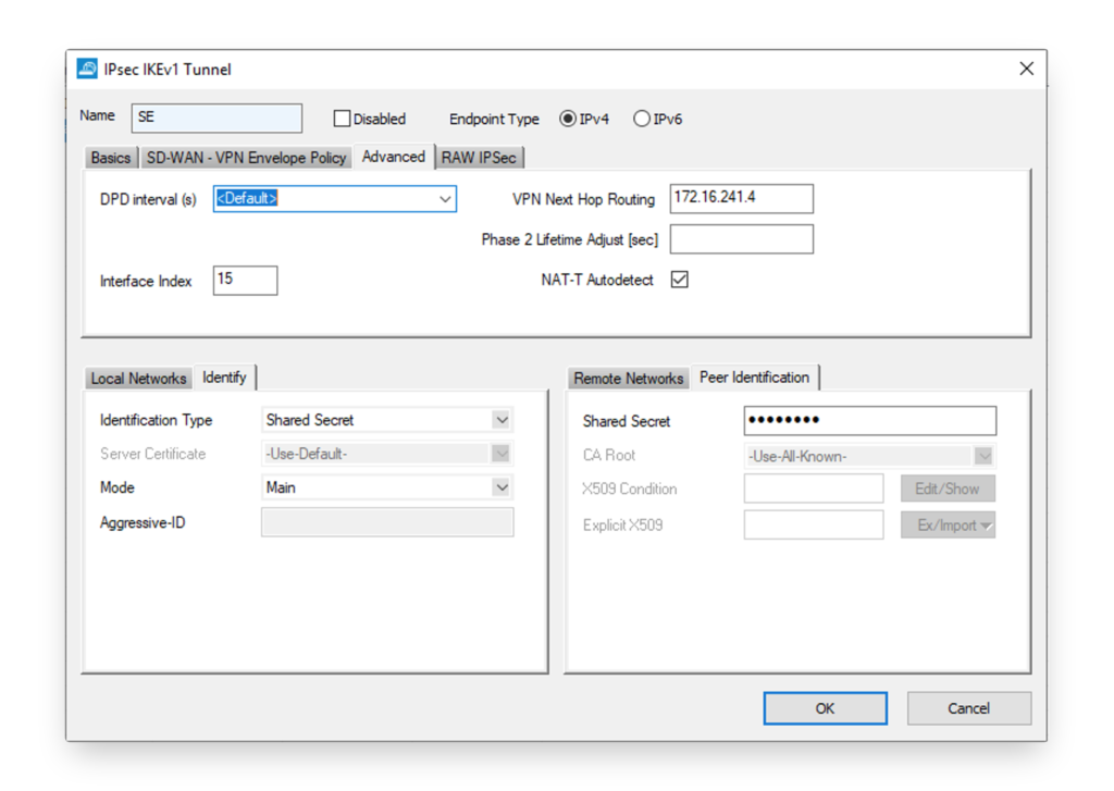
Next up is the IPSEC VPN configuration in Configuration > Box > Virtual Servers > Assigned Services > Site to Site > IPSEC IKEv1 Tunnels. Lock your configuration, right mouse click and select ‘New IPsec IKEv1 Tunnel’. Fill in the IPSEC tunnel settings. The ‘Local IKE Gateway’ can be set to 0.0.0.0 when you have a dynamic public IP or you can set it to the static public IP.
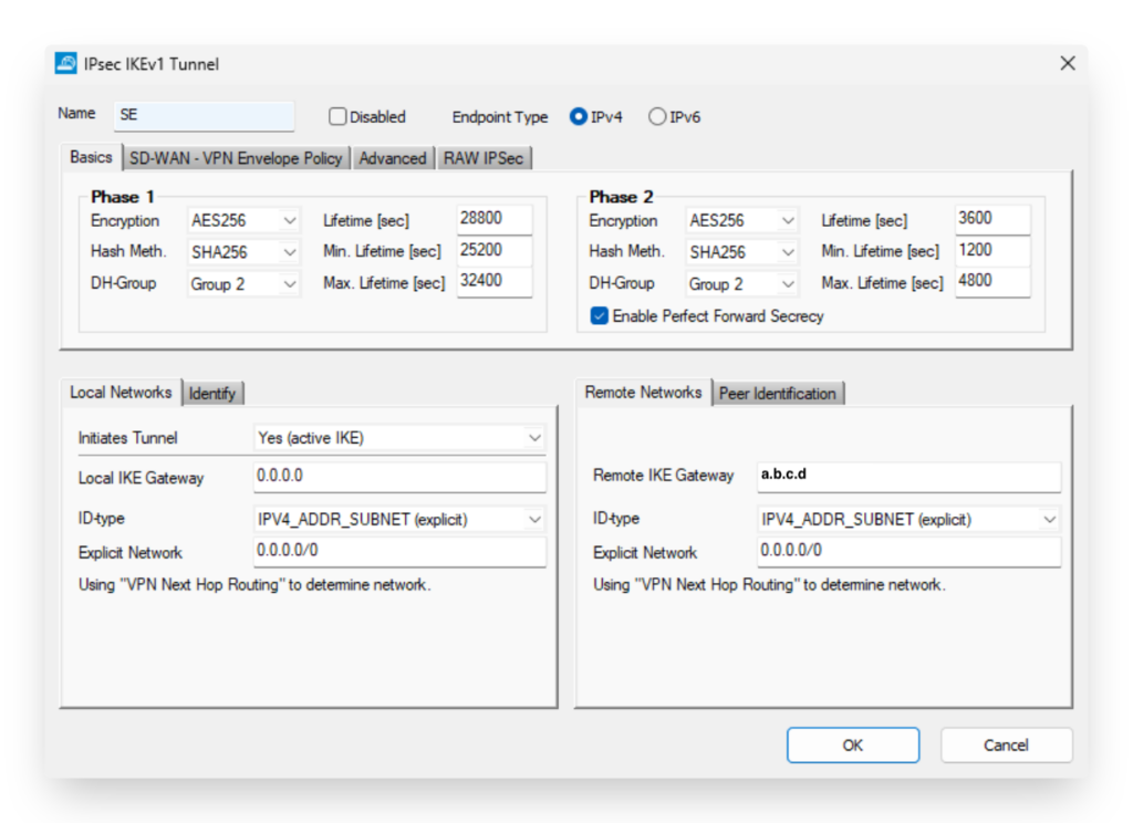
Notice that you need to replace the a.b.c.d with the public IP of the FortiGate side.
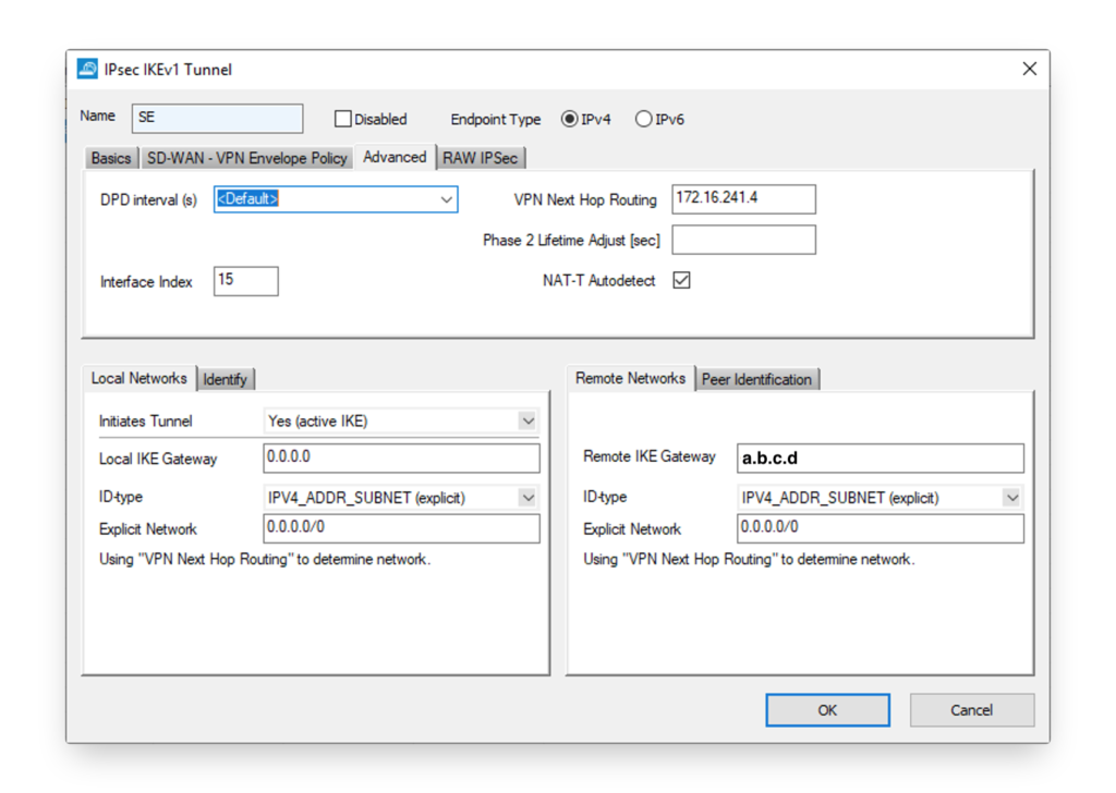
In the Advanced tab, the interface needs to be configured as well as the IP address in the VPN tunnel on the FortiGate side. In the setup explained in this blog post it is ‘172.16.241.4’.
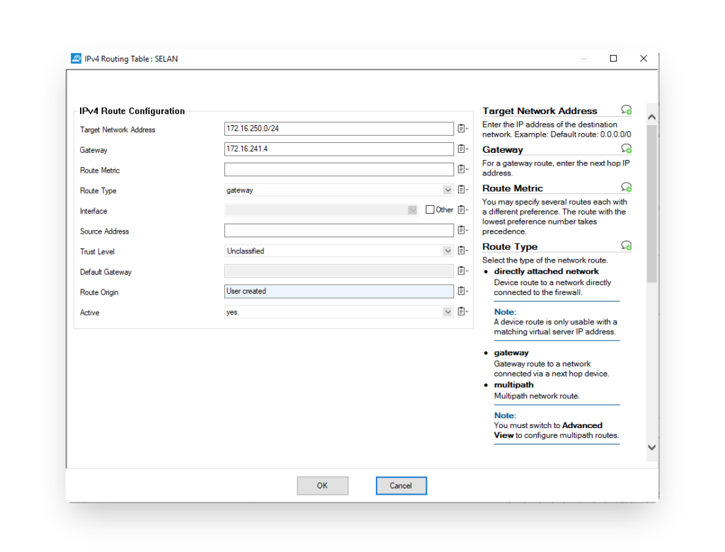
Routing
Once the IPSEC tunnel is configured, the routing should be configured. In the Configuration > Box > Network > Routing section you can configure the different routes to the networks behind the FortiGate.
Once configured, it is important that you activate the network settings in Control > Box > Activate new network settings. Beware that this could cause a network interruption. It is best to select the failsafe option. In case the applied network configuration is unable to reach the internet and the central Control Center it will revert to the old network configuration after the preset time.
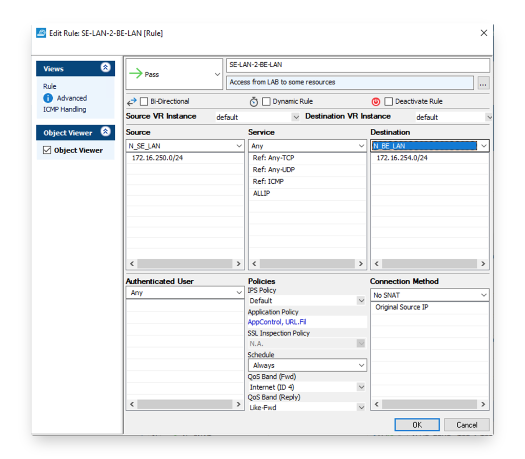
Firewall Policy
Last but not least, the firewall policy needs to be configured to allow the traffic between both sides. If address translation is required this can be configured here as well. In the image below, a firewall policy to allow traffic from the FortiGate side is allowed for all network protocols to the network behind the Barracuda firewall.
Debug
Of course, you can have some issues performing this setup. Most issues you will encounter is getting the IPSEC tunnel working and stable. I always joke that my grey hairs that appeared over the years came from the multiple debug sessions to get IPSEC tunnels up and running.
Make sure you try to read the logs and learn to interpret them on both side. Try to verifiy which phase is not established and look at the configuration. You might have missed a small setting. Also check the error codes in the logs and debug output. They will guide you in the right direction.
After each debug session, I feel a sense of accomplishment. There is in most cases a solution to your IPSEC config challenge. Never give up. Where possible to baseline everything in a LAB.
FortiGate
Get started on the CLI with the steps outlined on these links.
- https://kb.fortinet.com/kb/documentLink.do?externalID=FD46611
- https://docs.fortinet.com/document/fortigate/6.2.5/cookbook/044240/ipsec-related-diagnose-command
- https://docs.fortinet.com/document/fortigate/6.2.5/cookbook/834425/understanding-vpn-related-logs
Barracuda CloudGen Firewall
- https://campus.barracuda.com/product/cloudgenfirewall/doc/79462880/ipsec-vpn-tunnels/
- https://campus.barracuda.com/product/cloudgenfirewall/doc/73719167/ipsec-ikev1-log-messages-and-troubleshooting/
Good luck!
Hello JVHOOF,
Thank you for this great article, I was able to climb the tunnel without worry.
However, the routing does not work.
At no time did I see where the IP 172.16.241.4 should be specified on the fortinet. Can you tell me where to apply it?
Thank you
The article has been updated with a screenshot and config to configure the VPN tunnel interface on the FortiGate linked to the external network interface.
hmm.. why is there no entry of lifetime of phase 1 and phase2 in the baracuda.. is the standard 28800/3600 ? or what happens if you leave them open? mostly i have a better feeling if i explizitly but the times in. btw. why is nat-t autodetect checked.. disable it if necessary
The article has been updated with a screenshot of the IPSEC lifetime parameters. On the FortiGate you can indeed disable NAT-T if you are not behing NAT. Having it enabled will let the FortiGate to detect NAT-T and enable it when needed.